ASC 3 Speed Close Ratio Fixed Gear
The ASC was a 3 speed fixed gear hub produced by Sturmey-Archer between late 1945 and 1956. The first couple of years of production were exported and British clubmen could not buy one until 1948, when an alloy shelled version was introduced in the UK. The ASC was a close ratio hub, top gear being direct drive and the other two gears drops of 10% and 25%. It is clearly a very robust hub, but not quite the glittering success that Sturmey-Archer had hoped for. They didn't anticipate the ever growing popularity of the derailleur, and the ASC had rather more backlash than the clubmen were hoping for.
The hub on this page was bought recently by my brother Mike, who also dismantled it and put it back together. He says "A couple of the photos are just to show how things work - e.g. axle assembly. You can't put it back together like that, because clutches etc. need to go on first". Also "Direct drive is third gear. Second gear has a driven sun, to reduce the ratio. First gear has the fixed sun, to have maximum reduction". He estimated the backlash at 3o, less in top gear than the other gears.
For a long time now the ASC has been a rare and very collectable hub, still capable of being used if need be. Since riding fixed wheel bicycles regained popularity in the early part of the 21st century, Sturmey-Archer have reintroduced a 3 speed fixed gear hub to their range, the S3X. You might expect that Sun-Race (owners of S-A) would simply go back to the existing design, but they have completely re-engineered the hub for modern manufacturing. Certain internal parts perform similar functions but it all looks different. The main similarity of both hubs is that they have the primary planet cage connected solidly to the hub shell.
The ASC to me looks like a cross between an AW and an FM, with 4 planets like an AW and the second stage epicyclic train of an FM. It shares the FM's unusual driven sun. It is definitely very robustly built. They must have thought about the pedalling power that was likely to be put into it. On the example shown here, the sprocket had taken a serious beating, all teeth being hook shaped. Whoever owned the hub must have ridden it thousands of miles with powerful legs. Keep that in mind when you see the condition of the internal mechanism.
All of the photos may be clicked on to get larger versions.
| Mike's ASC, new to him. He had wanted one for many years and it had seemed like the holy grail of hubs. ebaY came up with the goods; a very nice condition alloy shell ASC. It had been suggested that Sturmey never made an ASC with a steel shell. | 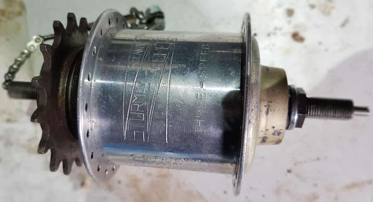 |
| The GB patents were awarded. Wonder if they ever got a patent in Taiwan? | 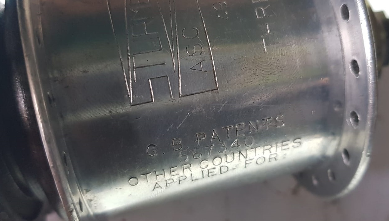 |
|
Just look at the shape of those sprocket teeth! Step 0. Ok, it's now or never. Thunderbirds are go. |
 |
| Step 1. Unscrew the lockring and pull off the spacers and sprocket. Note that the sprocket centre hole is much larger than the usual Sturmey sprockets. | 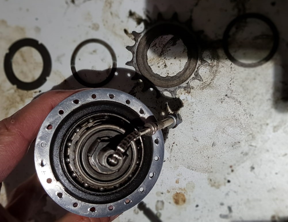 |
| Step 2. Remove the toggle chain and indicator rod, the cone locknut, tab locking washer, and right hand cone Lift off the driver and ball race. Take out the clutch spring with its collar and the axle key collar. That's a lot of parts but very similar to other Sturmey hubs. Refer to the AW stripdown if need be. | 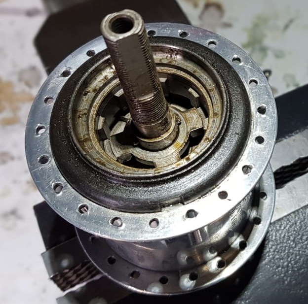 |
| Step 3. Remove the left hand locknut, washer and cone. | 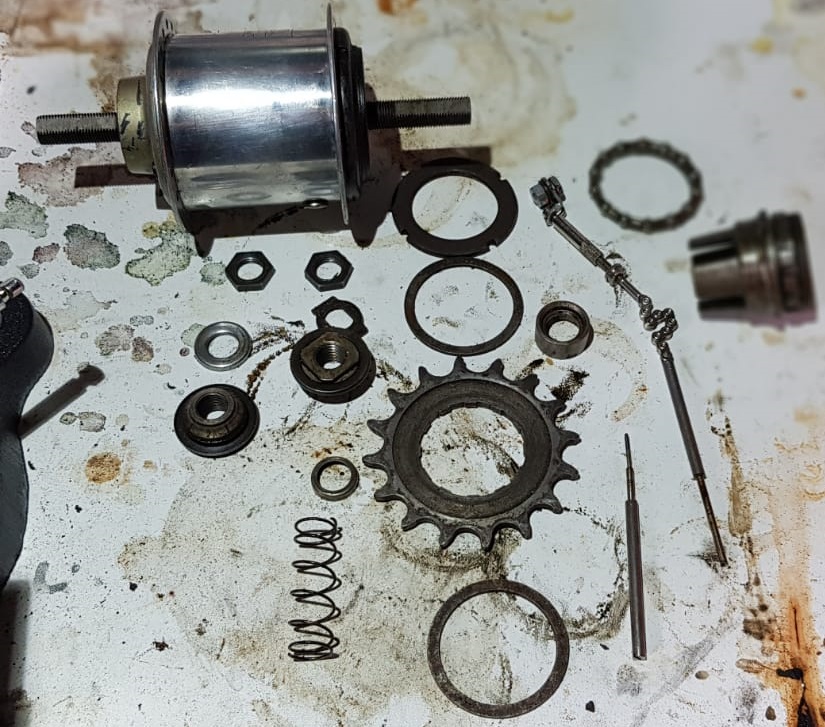 |
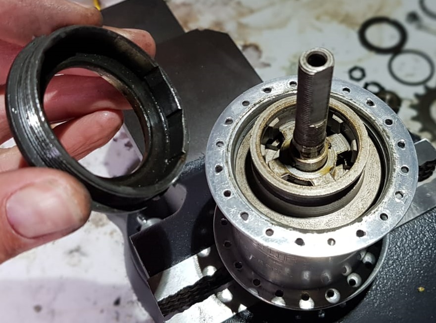
| Step 4. You need to unscrew the ball ring from the shell and this is a good method to loosen it off. | 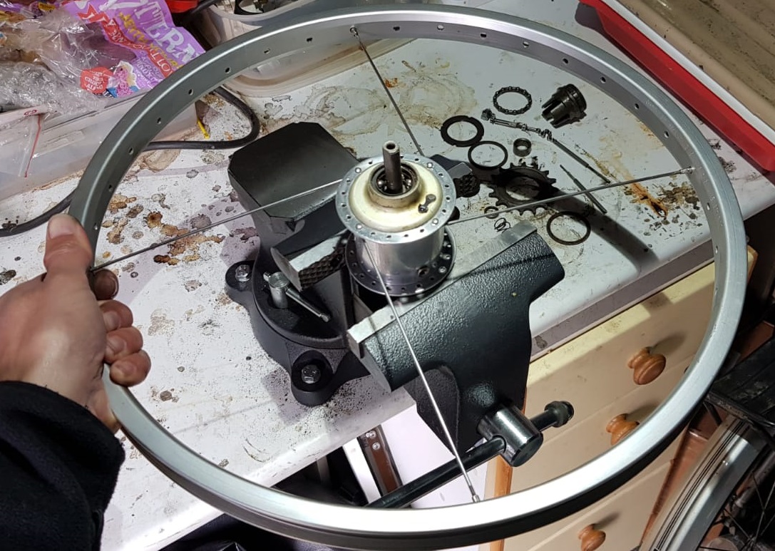 |
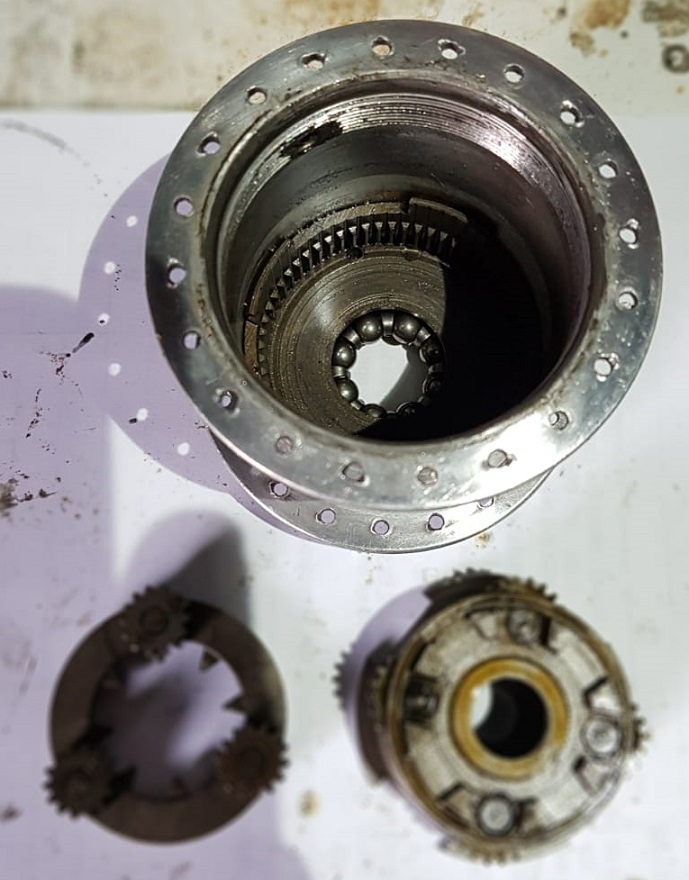
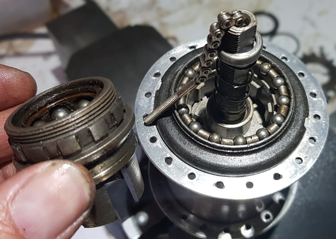
| Step 5. Finish unscrewing the ball ring by hand. A very clean looking mechanism! Note that there are notches for pawl engagement in the right hand ball ring but there are no pawls in the top of the mechanism. The ball ring must be shared with another hub design. |
 |
| Step 6. Lift off the annulus. The teeth are in perfect order, hardly run in. There is no evidence of wear on the clutch or any of the parts it engages with, which is quite remarkable. |  |
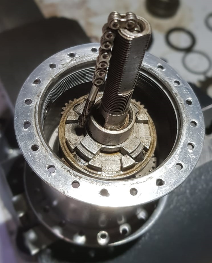
| Step 7. The mechanism looks almost factory fresh. A little bit short of oil; there should be a couple of teaspoons in there according to Sturmey's specifications. All the planet teeth look perfect. It looks much tougher than an AW but the pinion gears are a similar size. Note the cutouts in the planet cage right hand flange to engage with dogs on the hub shell. |
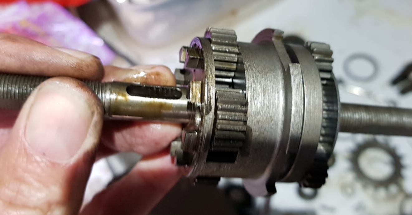 |
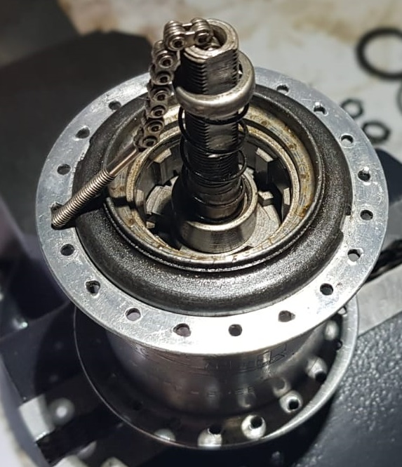
| Step 8. Lift off the primary planet cage. The secondary train looks a lot like an FM's. There may be some shared parts between these hubs. Surprisingly, that large spring must be compressed by the gear trigger to engage a gear! Note that the small sun gear on the left is not permanently locked to the axle. It is actually driven by the secondary planet train in 2nd gear. In 3rd, it is floating and in 1st it is dogged to the axle. |
 |
| Step 9. Here, the internals shown in Step 8 are mostly dismantled. Only the annulus and clutch assembly are not shown so the hub is not especially numerous in terms of parts, despite its two epicyclic trains. Nevertheless it's not easy to understand how it works! The small sun gear is part of a 4 pronged driver that has the large spring coiled around it. It slides into place from the left side on the shiny part of the axle. The clutch that works with it has dogs that mesh with the castellations on the axle. |
 |
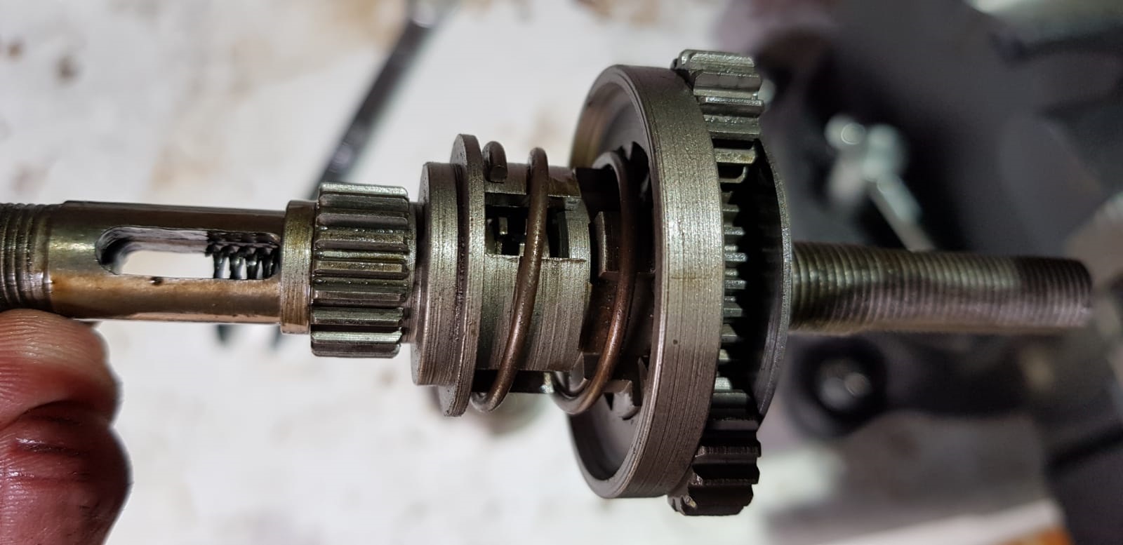
| Step 10. Showing how the selection parts work with the central spring. The left hand "top hat" with the axle key in will need to be removed again to build the axle sub assembly. |
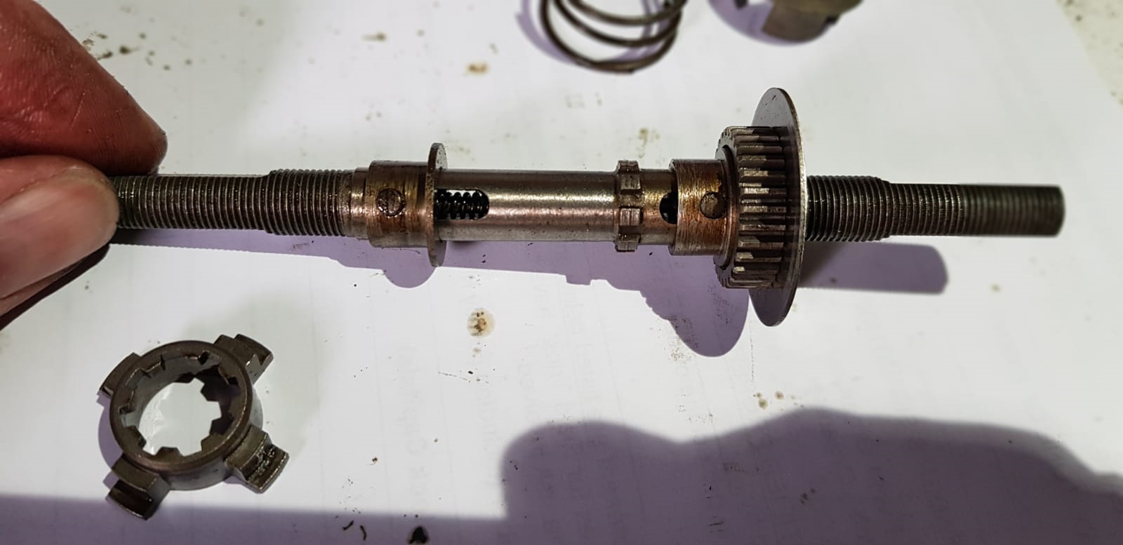 |
| Step 11. Starting the rebuild of the axle sub-assembly. Here are all the parts laid out in order. On this photo you can see that the large sun has a square hole and fits over the square section of axle on the left, so it is permanently locked to the axle. |
 |
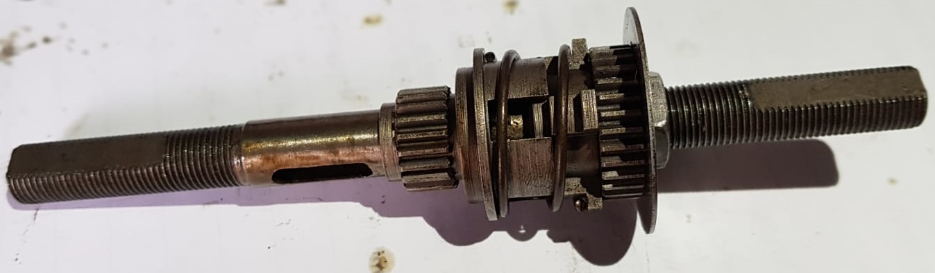
| Step 12. ...and all put together. The axle assembly has been flipped left to right. This is just to show how the gear engagement controlled by the large spring works. In fact it's necessary to take off some parts again to get the secondary epicyclic train in place. |
 |
| Step 13. Here are all the parts for the two epicyclic gear trains. |  |
| Step 14. The secondary epicyclic train (with 3 planets on the left) meshes with the annulus machined into the ball cup on the left hand side of the hub shell. (Or at the bottom of the hub shell in this photo). |
 |
| Step 15. Let's continue with the rebuild. Remove the parts that are in the way and put the secondary epicyclic train sub-assembly on. | 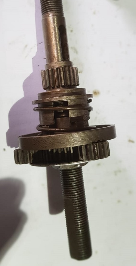 |
| Step 16. Slide the primary epicyclic train (planet cage and planets) on to the small sun that rotates on the axle. |  |
| Step 17. Put on the clutch collar, the 4 pronged clutch and push the axle key through the holes. Screw in the toggle chain and indicator rod to ensure that it will pass through the holes in both axle keys. |  |
| Step 18. Lower the mechanism into the shell. Rotate to engage the secondary planets with the annulus on the left hand ball ring. Drop the axle key collar into place. |
 |
| Step 19. It's now a race to the line. Slide on the clutch spring and clutch spring collar. Screw the right hand ball ring into place. You can add two teaspoons of 4 stroke lawnmower oil now if you are going to use the hub! |
 |
| Step 20. Grease the ball ring (driver) bearing and the wheel bearing. Engage the driver with the clutch arms by rotation and screw on the right hand cone. Screw the cone right up finger tight and back off 1/2 to 3/4 of a turn. Lock in place with the tab washer and screw on the cone locknut. |
 |
| Step 21. Refit a spacer, the sprocket, another spacer and screw on the lockring. Grease and replace the left hand ball race, then screw on the left hand cone, adjust the wheel bearings and lock the cone in place with the locknut. These steps are all very similar to the AW reassembly process. |
|